How to configure a FadeCandy RGB LED Controller
Related Config File Sections:
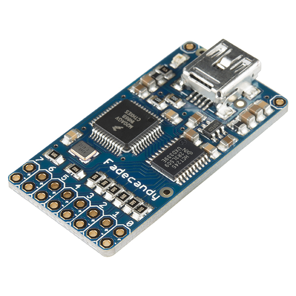
MPF allows you to use a FadeCandy LED controller to drive the LEDs in your pinball machine. A FadeCandy is a small, cheap (\$25) USB controller which can drive up to 512 serially-controlled RGB LEDs.
You can use the FadeCandy in place of connecting your LEDs to a P-ROC/P3-ROC controller, or you can choose to drive some LEDs via your primary pinball controller and some via the FadeCandy. (This is useful if you want to use more LEDs than what your controller platform supports.)
You can connect up to four FadeCandy boards to drive a total of 2048 LEDs (Which would be insane. And awesome.)
You can read more about the FadeCandy on the main page of the FadeCandy software repository in GitHub or on Adafruit or SparkFun, where you can buy one for \$25. The FadeCandy is very advanced, offering advanced light processing capabilities such as dithering and interpolation that are not available if you just control LEDs directly.
If you're not familiar with the FadeCandy, check out this intro video from SparkFun:
Overview video about serial LEDs:
1. Understanding all the parts and pieces
Before we dig in to setting up a FadeCandy with MPF, let's look at how all the various components will fit together:
- The FadeCandy is a piece of hardware that talks to your host computer via USB. (So if you use it in a pinball machine then you'll have two devices connected via USB---your pinball controller and your FadeCandy.)
- The FadeCandy hardware is driven a FadeCandy server software that you'll run on your host computer along side the MPF game engine and the MPF media controller. The FadeCandy server talks to the FadeCandy hardware via a USB driver.
- The FadeCandy server receives instructions for LEDs connected to the FadeCandy via a protocol called Open Pixel Control (OPC).
Putting it all together, MPF talks to the FadeCandy server via OPC, and the FadeCandy server talks to the FadeCandy hardware via USB.
2. Download the FadeCandy package from GitHub
The first step is to download the FadeCandy package from GitHub. You can unzip it to wherever you want.
3. Install the FadeCandy drivers
When I plugged the FadeCandy hardware into my Windows computer, the driver did not install automatically. Running the fcserver (next step) said it was installing the drivers, but that didn't do anything for me. (It just said "this may take awhile" but I killed it when it didn't seem like it was actually doing anything.)
In my case, I googled and found this procedure to build custom .inf files for Windows. It seems crazy but it wasn't too bad. I had to build two: One for the FadeCandy device and one for the FadeCandy boot loader. Either way, you can follow the docs and the forums around the FadeCandy and get it setup.
4. Setup the fcserver
The FadeCandy download package includes pre-built binaries for Mac and Windows. On Linux you can compile it. Again, the FadeCandy documentation has details about how to do this.
At this point you should be able to run the fcserver and to talk to your FadeCandy LEDs and get them to do things. There are a bunch of sample apps in the FadeCandy package that are kind of cool.
5. Set your LEDs to use the "fadecandy" platform
Next you need to configure your LEDs in MPF to use the fadecandy
platform. By default, all types of devices are assumed to be using the
same platform that you have set in the
hardware: of your machine config
file. So if your platform is set to fast, MPF assumes your LEDs are
connected to a FAST controller, and if your platform is set to p_roc
or p3_roc, MPF assumes your LEDs are connected to a PD-LED board.
To configure MPF to use FadeCandy LEDs, you can add an entry to the
hardware: section of your machine config to tell it to override the
default platform for your LEDs and to instead use the fadecandy
platform, like this:
hardware:
  platform: p_roc
  driverboards: pdb
  lights: fadecandy
See the Mixing-and-Matching hardware platforms guide for more information about setting device-specific default platforms versus overriding the platform for individual devices.
6. Understanding FadeCandy LED numbering
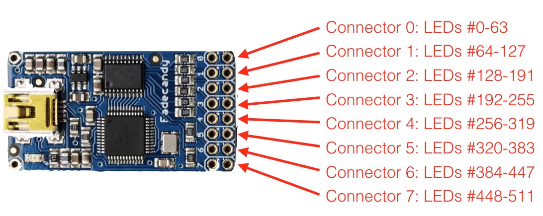
The FadeCandy hardware has 8 connectors for LEDs, each of which can support up to 64 RGB LEDs (for 512 RGB LEDs total). The connectors are numbered 0-7.
The individual LED numbers are sequential across channels. The first LED on Connector 0 is #0, the second is #1, etc., up #63 on Connector 0. Then Connector 1 picks up where Connector 0 leaves off, with the first LED on Connector 2 being #64, and so on. The FadeCandy doesn't actually know how many LEDs are connected to each connector, so the first LED on Connector 1 is always LED #64 even if you have less than 64 LEDs physically connected to Connector 0.
The following diagram explains how the numbering works:
Consider the following config:
lights:
  l_led0:
    number: 0    # first LED on connector 0
  l_led1:
    number: 1    # second LED on connector 0
  l_led2:
    number: 128    # first LED on connector 2
(If you're familiar with the Open Pixel Control protocol, all of the LEDs on a single FadeCandy board are on the same OPC channel, which is technically what you're specifying with the number before the dash.)
6a. Numbering with multiple channels
You can also assign different OSC channels to your connectors. This has certain performance advantages and allows nicer numbering.
Start your fadecandy server with the following config:
{
    "listen": ["127.0.0.1", 7890],
    "verbose": true,
    "color": {
        "gamma": 2.5,
        "whitepoint": [1.0, 1.0, 1.0]
    },
    "devices": [
        {
            "type": "fadecandy",
            "serial": "YOUR_FADECANDY_SERIAL",
            "map": [
                [ 0, 0, 0, 64 ],
                [ 1, 0, 64, 64 ],
                [ 2, 0, 128, 64 ],
                [ 3, 0, 192, 64 ],
                [ 4, 0, 256, 64 ],
                [ 5, 0, 320, 64 ],
                [ 6, 0, 384, 64 ],
                [ 7, 0, 448, 64 ]
            ]
        }
    ]
}
Replace YOUR_FADECANDY_SERIAL with the serial of your fadecandy. The serial will be shown on the console of fcserver when connecting your fadecandy.
Then configure your lights as follows:
lights:
  l_led0_0:
    number: 0-0    # first LED on connector 0
  l_led1_0:
    number: 1-0    # first LED on connector 1
  l_led1_1:
    number: 1-1    # second LED on connector 1
  l_led7_20:
    number: 7-20    # twentyth LED on connector 7
6b. Numbering with multiple Fadecandy Boards
If you want to use multiple FadeCandy boards we suggest the following config:
{
    "listen": ["127.0.0.1", 7890],
    "verbose": true,
    "color": {
        "gamma": 2.5,
        "whitepoint": [1.0, 1.0, 1.0]
    },
    "devices": [
        {
            "type": "fadecandy",
            "serial": "YOUR_FADECANDY_SERIAL1",
            "map": [
                [ 0, 0, 0, 64 ],
                [ 1, 0, 64, 64 ],
                [ 2, 0, 128, 64 ],
                [ 3, 0, 192, 64 ],
                [ 4, 0, 256, 64 ],
                [ 5, 0, 320, 64 ],
                [ 6, 0, 384, 64 ],
                [ 7, 0, 448, 64 ]
            ]
        },
        {
            "type": "fadecandy",
            "serial": "YOUR_FADECANDY_SERIAL2",
            "map": [
                [ 8, 0, 0, 64 ],
                [ 9, 0, 64, 64 ],
                [ 10, 0, 128, 64 ],
                [ 11, 0, 192, 64 ],
                [ 12, 0, 256, 64 ],
                [ 13, 0, 320, 64 ],
                [ 14, 0, 384, 64 ],
                [ 15, 0, 448, 64 ]
            ]
        },
        {
            "type": "fadecandy",
            "serial": "YOUR_FADECANDY_SERIAL3",
            "map": [
                [ 16, 0, 0, 64 ],
                [ 17, 0, 64, 64 ],
                [ 18, 0, 128, 64 ],
                [ 19, 0, 192, 64 ],
                [ 20, 0, 256, 64 ],
                [ 21, 0, 320, 64 ],
                [ 22, 0, 384, 64 ],
                [ 23, 0, 448, 64 ]
            ]
        }
    ]
}
Replace YOUR_FADECANDY_SERIAL1, YOUR_FADECANDY_SERIAL2 and YOUR_FADECANDY_SERIAL3 with the serials of your fadecandy boards (you can use more or less than three). The serial will be shown on the console of fcserver when connecting your fadecandy.
Afterwards, configure your lights as follows:
lights:
  l_led0_0:
    number: 0-0    # first LED on connector 0 on board 0
  l_led1_0:
    number: 1-0    # first LED on connector 1 on board 0
  l_led1_1:
    number: 1-1    # second LED on connector 1 on board 0
  l_led7_20:
    number: 7-20    # twentyth LED on connector 7 on board 0
  l_led8_0:
    number: 8-0    # first LED on connector 0 on board 1
  l_led8_1:
    number: 8-63    # last LED on connector 1 on board 1
  l_led17_1:
    number: 17-1    # second LED on connector 1 on board 2
7. Understanding MPF light numbers and channels
In MPF lights abstract
a light source which emits arbitrary colors. However, this is not true
for all real lights. Some support only white (GIs), others only a
single-color (i.e. red inserts) and others support full RGB. For that
reason MPF knows
light numbers and channel numbers. Internally, a light consists of one or multiple channels.
For instance, a single-color GI will contain a single white channel.
While a RGB light will control a red, green and a blue channel. A white
light behind a red insert should be a single red channel (because it
cannot emit other colors through the red insert). You can configure
those channels using the channels setting or use start_channel and
type to define the channels. See
/mechs/lights/index for details.
However, in most cases a platform supports one type of lights (per
subtype) this would be overly verbose and we added the number
setting for configuring lights in the common platform way. For instance
a platform for GIs will configure single channel white lights or a
serial LED controller will configure RGB lights with three channels.
Fadecandy assumes RGB lights by default. For everything else (i.e. RGBW) you have to use channels.
Light Numbers
Fadecandy numbers use the format: osc_channel-number
If you mapped OSC channels as described in (6b/c) set them as
osc_channel. number is the index of your light in the chain.
Internally, Fadecandy assumes three channels per LED (RGB/GRB WS2811/WS2812 LEDs).
Channels
Fadecandy channels use the format: osc_channel-channel_index
channel_index is number * 3. This is because serial LEDs are
traditionally RGB (or GRB) LEDs with exactly three channels. However,
this is not true for RGBW or similar LEDs which do not work with this
style of numbering. Luckily, you can chain them instead and have MPF
calculate the internal channels for you:
lights:
  led_0:
    start_channel: 0-0
    subtype: led
    type: rgb    # will use red: 0-0, green: 0-1, blue: 0-2
  led_1:
    previous: led_0
    subtype: led
    type: rgbw   # will use red: 0-3, green: 0-4, blue: 0-5, white: 0-6
  led_2:
    previous: led_1
    subtype: led
    type: rgbw   # will use red: 0-7, green: 0-8, blue: 0-9, white: 0-10
See WS2811 and WS2812 LEDs in Pinball for details.
8. Launch the fcserver
In order for MPF to communicate with the FadeCandy, the fcserver has to
be running. Refer to the FadeCandy documentation for instructions for
this. On Windows, for example, it's just called fcserver.exe.
There are several command line options you can use with the server, though you don't need any of them with MPF unless you have more than one FadeCandy board connected.
You should launch fcserver in its own window since it will take over the console when it's running. It's also safe to keep it running all the time, or you can add it to a batch file to run it automatically. On my system, the fcserver puts some error message on the screen about not being able to connect to something, but everything still works even with that message continually being written to the console. (I think it's something to do with the P-ROC's FTDI driver? It only comes up when the P-ROC is on.)
9. Additional FadeCandy LED options
The FadeCandy hardware supports some advanced options which are configured in the fadecandy: section of your machine configuration file. Specifically, you can set the keyframe interpolation, dithering, gamma, white point, linear slope, and linear cutoff. The defaults should be fine for almost everyone, though you can go nuts if you want.
10. Color Correction
If you are using RGB LEDs, they might not be perfectly white when you turn them on. They might be pinkish or blueish instead depending on the brand of the LED. To a certain extend this is normal/expected and you can compensate for it by configuring hardware color correction in the fadecandy. If you need more than one correction profile (e.g. for multiple LED models) you need to fall back to software color_correction profiles in light_settings. Hardware correction should be preferred and give you much more dynamic range.
What if it did not work?
Have a look at our fadecandy hardware troubleshooting guide.
Something missing or wrong? You can fix it!
This website is edited by people like you! Is something wrong or missing? Is something out of date, or can you explain it better?
Please help us! You can fix it yourself and be an official "open source" contributor!
It's easy! See our Beginner's guide to editing the docs.
Page navigation via the keyboard: < >
You can navigate this site via the keyboard. There are two modes:
General navigation, when search is not focused:
- F , S , / : open search dialog
- P , , : go to previous page
- N , . : go to next page
While using the search function:
- Down , Up : select next / previous result
- Esc , Tab : close search
- Enter : go to highlighted page in the results