How to configure opto switches
Related Config File Sections:
Optical switches (short optos) are common in pinball machines. They usually cover ranges up to 10cm and are used in places where normal roll over switches cannot be used (e.g. because a lane is too wide or on a ramp). Optos are also commonly used in ball troughs.
Electronical details
Electronically they consist of a sender and a receiver. The sender is
usually connected to 5-12V power with a current limiting resistor in
line (to limit the current to about 50-70 mA). Alternatively, a constant
current driver may be used (more expensive but better for the sender).
The receiver is usually connected to a direct input on a switch board
(they cannot be used in a switch matrix without further logic PCBs).
Most direct inputs have an internal pull up which will pull the level to
VCC (usually around 10 kOhm). The opto receiver will then pull the
current to GND when it receives light from the sender. Once the light
beam is interrupted the receiver will stop conducting and the input will
go up to VCC again. For this reason, the input will be closed when the
beam is not interrupted and open when the opto is interrupted. This is
exactly inverse than a normal switch and you have to configure your opto
as normally closed (short NC) for that reason. If your opto is using
an additional PCB for optos it might invert the signal and revert this
effect (just try normally closed first and change it later -it will not
break anything).
TODO: Add electronical drawing for sender and receiver.
Video about wiring optos:
Brightness and Current
The brightness of IR diodes (and diodes in general) depends only on the current flowing through the diode. Usually IR diodes (i.e. the famous QED123) drop about 1.7V forward voltage. However, this is not a constant and will fluctuate depending on manufacturer tolerances. That means that at about 1.7V current will start to flow through the diode and it will emit (IR) light. Unfortunately, just connecting it to 1.7V is not sufficient because the current is non-linear for LEDs. Below the forward voltage (i.e. 1.7V) the currency is 0 and above the forward voltage it increases exponentially. According to the specifications most IR LEDs should use run at 20mA. However, in pinball machines 50-70mA is used because it allows larger distances. Unfortunately, that is also the reason why transmitters often break in pinball machines because more current makes diodes age faster. 100mA is the absolute maximum rating for most LEDs which means that the part is not indented to be operated at this current for prolonged periods. Since the current increases exponentially above the forward voltage, the forward voltage has huge tolerances during manufacturing and power supplies have tolerances, too, it is absolutely necessary to limit the current instead of regulating the voltage. There are two approaches which will be described in the following.
Constant Current Drivers
Technically, the best solution to drive a IR sender is a constant current driver. However, it is quite costly compared to the next solution. In some cases a constant current driver might be embedded on your optos (see below at the Stern Spike optos). In addition, there are opto driver boards which contain constant current drivers. The main advantage of constant current drivers is that they are not affected by any fluctuation in the supply voltages or manufacturing tolerances/aging of the IR diode. Expect significant higher lifetimes of your transmitters with those drivers.
Common parts:
- Stern Spike Trough Boards
- FAST 4-Channel 12v Constant Current Opto Emitter Driver
- Stern Spike Opto Amplifier - 520-5239-01
Have a look at our PCB section of hardware.missionpinball.org for DIY designs. Have a look at /config/switches for details about breakout boards.
Current Limiting Resistor
A very cheap and common solution is to use a resistor in line with your transmitter to limit the current. In practice, this will result in varying brightnesses depending on manufacturing tolerances of the resistor (10%) and the diode (unknown but high). Additionally, changes in the supply voltage will also affect the brightness. For this reason, it is wise to design your resistor a bit lower to account for some tolerances.
If your supply voltage is 5V you probably want a 56ohm or 68ohm resistor at 1/2watt in line with your sender (assuming a forward voltage of 1.7V and 50mA forward current). For 12V you need a 220ohm at 1 watt which will get very hot (do not use a standard 1/2watt resistor).
Common parts:
- 4x Opto board - #600-0256-00
Have a look at our PCB section of hardware.missionpinball.org for DIY designs. Have a look at /config/switches for details about breakout boards.
Common Parts in Pinball Machines
In the following we will describe some common parts and how to connect them.
Williams/Bally Optos
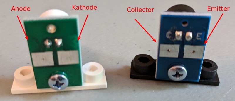
In most platforms with direct inputs you can directly connect a receiver
to an input. You connect the collector to the input (C) and the
emitter (E) to ground. Consult the documentation of your hardware
platform for details.
For the transmitter connect the kathode (K) to ground and the anode
(A) to a current limiting resistor. Connect the resistor to power. DO
NOT omit the resistor to power without any current limiting or it will
break/burn.
Part numbers:
- Transmitter: A-16908 or A-14231
- Receiver: A-16909 or A-14232
Diodes used (in case you need to replace them):
- Transmitter: QED123
- Receiver: QSD124 or QSD124A4R0 (Pinball part numbers: 5163-14114-00 or 5163-12732-00)
Data East/Sega/older Stern Optos
TODO: Add a picture of those transceivers
Data East/Sega and later Stern used a diode which can serve as either transmitter or receiver called "transceiver". The advantage of this solution is that you only need one type of parts. Electronically they work similar to Williams/Bally optos.
Part numbers:
- Transceiver: 500-6775-00/500-6775-01 or 500-6747-00
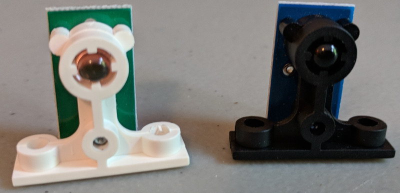
Stern Spike Optos
Labels on Stern Spike optos looks different but they work similarly:
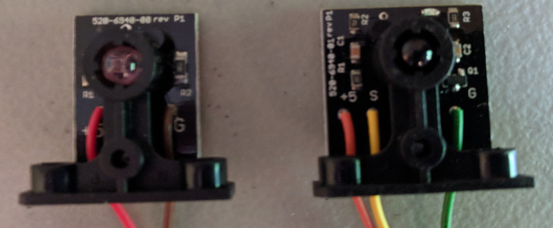
On the transmitter (left) connect +5 to 5V and G to GND. A current
limiting resistor is not required since it is embedded on the sender.
The receiver also connects +5 to 5V and G to GND. Additionally,
connect signal S to your input.
Part numbers:
- Transmitter: 520-6940-00/515-0215-00
- Receiver: 520-6940-01/515-0215-01
Multimorphic Optos:
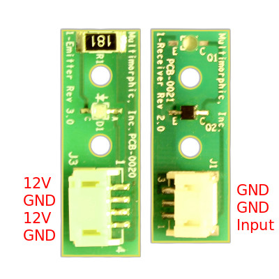
Multimorphic produces and sells optos with a JST connector. The transmitter contains a current limiting resistor for 12V (you only have to connect one of the 12V and GND pins). You don't need an additional resistor but you are also bound to 12V. They might work at 5V but the range will be much lower. Though the surface mount resistor on the transmitter board is designed to run "hot," it still requires a surrounding air gap to dissipate heat. 3D printed parts mounted against this resistor will melt.
Part numbers:
- Transmitter: PCBA-0019-EO03, PCBA-0019-EI03, PCBA-0020-CI03, PCBA-0020-CO03
- Receiver: PCBA-0021-EI03, PCBA-0021-CI03, PCBA-0021-EO03, PCBA-0021-CO03
Config
You can configure a normally closed opto like this:
switches:
  trough1:
    number: 81    # number depends on your platform
    type: 'NC'    # normally closed
  orbit_opto:
    number: 23    # number depends on your platform
    type: 'NC'    # normally closed
See switches: for details about the config options.
Something missing or wrong? You can fix it!
This website is edited by people like you! Is something wrong or missing? Is something out of date, or can you explain it better?
Please help us! You can fix it yourself and be an official "open source" contributor!
It's easy! See our Beginner's guide to editing the docs.
Page navigation via the keyboard: < >
You can navigate this site via the keyboard. There are two modes:
General navigation, when search is not focused:
- F , S , / : open search dialog
- P , , : go to previous page
- N , . : go to next page
While using the search function:
- Down , Up : select next / previous result
- Esc , Tab : close search
- Enter : go to highlighted page in the results