Connecting P/P3-Roc to your Computer
This page is about connecting the P/P3-Roc to your computer. It roughly covers connecting the bus between the nodes. For electronic details see the P-Roc section in the pinballmakers.com Wiki.
P-Roc
If you got a P-Roc just connect it to your computer using USB.
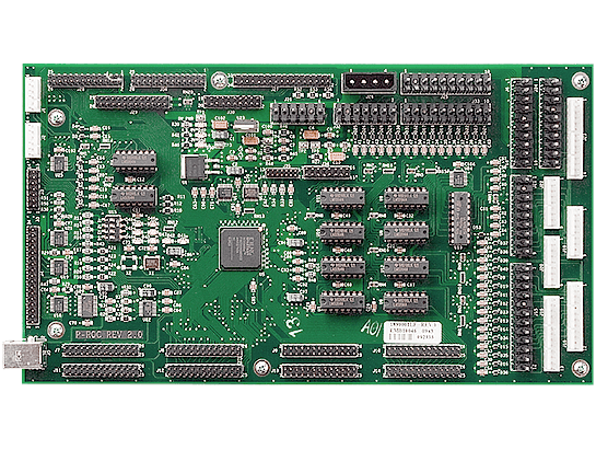
Then connect switches and driver according to the manual (see leds for specific machines). If you are using a PD-Master board see below for switches and drivers.
mpf hardware scan will show the firmware version and revision of your P-Roc if it is connected correctly.
P3-Roc
If you got a P3-Roc just connect it to your computer using USB.
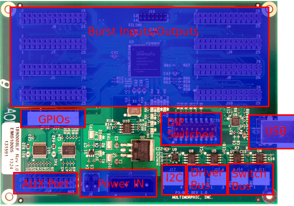
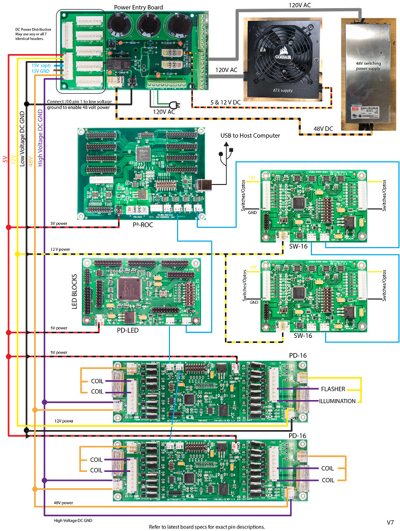
Connect all your SW-16 boards to the switch bus and all your PD-16 and PD-8x8 boards to your driver bus. Use twisted wires but connect + to + and - to - on all nodes.
mpf hardware scan will show the firmware version and revision of your P3-Roc if it is connected correctly.
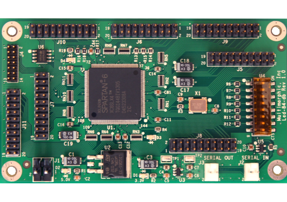
SW-16
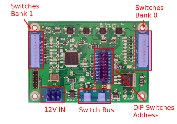
Set a unique address on every SW-16 board on your bus. Those addresses can overlap with the driver addresses. It does not matter on which of the two switch busses the boards are connected. Terminate the bus at the last board. See leds for how to configure those boards.
You can list all SW-16 using mpf hardware scan:
$ mpf hardware scan

Firmware Version: 2 Firmware Revision: 6 Hardware Board ID: 1
SW-16 boards found:
 - Board: 0 Switches: 16 Device Type: A3 Board ID: 0
 - Board: 1 Switches: 16 Device Type: A3 Board ID: 1
 - Board: 2 Switches: 16 Device Type: A4 Board ID: 2
PD-16/PD-8x8
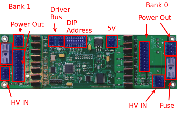
Set a unique address on every PD-16/PD-8x8 board on your bus. Those addresses can overlap with the switch addresses. However, they overlap with the PD-LED addresses so plan accordingly. It does not matter on which of the two driver busses the boards are connected. Terminate the bus at the last board. See leds and leds for how to configure those boards.
MPF and the P3-Roc do not know if those boards are connected as the communication is one-way only.
PD-LED
Set a unique address on every PD-LED board on your bus. Those addresses can overlap with the switch addresses. However, they overlap with the PD-16 addresses so plan accordingly. It does not matter on which of the two driver busses the boards are connected. Terminate the bus at the last board. See How to configure LEDs on the PD-LED (P-ROC/P3-ROC) for how to configure those boards.
MPF and the P3-Roc do not know if those boards are connected as the communication is one-way only.
What if it did not work?
Have a look at our troubleshooting guide for the P/P3-Roc.
Something missing or wrong? You can fix it!
This website is edited by people like you! Is something wrong or missing? Is something out of date, or can you explain it better?
Please help us! You can fix it yourself and be an official "open source" contributor!
It's easy! See our Beginner's guide to editing the docs.
Page navigation via the keyboard: < >
You can navigate this site via the keyboard. There are two modes:
General navigation, when search is not focused:
- F , S , / : open search dialog
- P , , : go to previous page
- N , . : go to next page
While using the search function:
- Down , Up : select next / previous result
- Esc , Tab : close search
- Enter : go to highlighted page in the results