How to configure a "SmartMatrix" RGB LED DMD
Related Config File Sections:
This guide explains how to connect a SmartMatrix RGB LED DMD to a pinball machine running MPF.
A SmartMatrix is a cheap (\$20) board that you attach to a Teensy (\$25) microcontroller which lets you connect an RGB DMD matrix display to the computer running MPF. It's a standalone solution which you can use to add an RGB DMD to a pinball machine that's using FAST Pinball, P-ROC/P3-ROC, or OPP controller hardware.
MPF supports several different types of RGB DMDs, and the SmartMatrix is just one of the options. More information about this type of display and other options that MPF supports is available in the Using an RGB full-color LED DMD documentation.
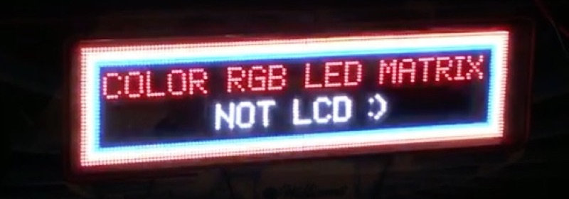
Here's an image of the SmartMatrix RGB DMD in action:
And a video which explains it all:
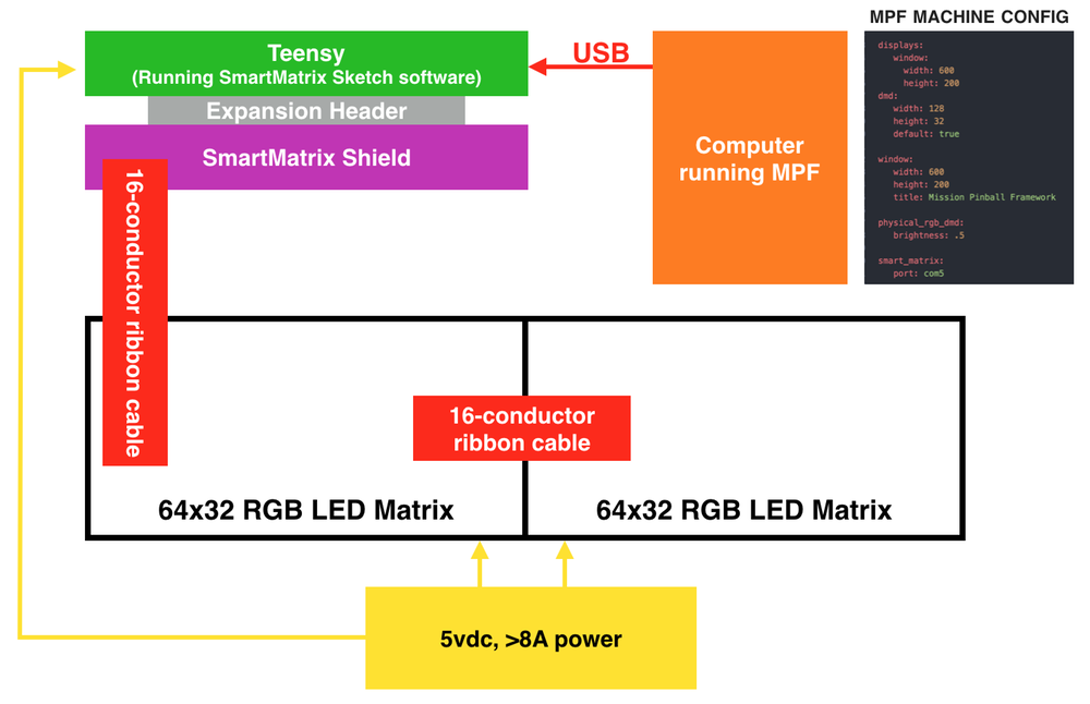
The following diagram shows how all the components fit together:
1. Buy all the parts you need
This solution is very much a "homebrew" solution that will require you to buy a lot of parts from various sources.
Alternatively, FAST pinball also offers a RGB DMD which contains controller, panels and mounting brackets (ask them directly since it is not currently listed on their website). If you go with this solution skip steps 1 to 3. You still need a power supply (step 4).
(1) The Panels
We originally had to buy the panels directly from China via AliExpress, but now FAST Pinball sells a kit. The FAST Pinball option is nice because the price is great and they also include a mounting bracket that fits a standard DMD cutout (ask them directly since it is not currently listed on their website).
If you buy the panels yourself on AliExpress, you'll pay about the same price for just the panels, you won't have a mounting bracket, and you'll have to deal with customer support from China. Also FAST tests the panels to make sure all the pixels work---a problem people were running into when buying from AliExpress.
(2) The Teensy
Once you have your panel, you need a way to talk to them via a computer. The panels use some kind of 16-pin signalling system which is some kind of standard in the gigantic advertising display industry.
The solution for MPF is to use a Teensy 3.2 or 3.5 (which is kind of like an Arduino). The Teensy is available from multiple sources for about \$20. Here's the link to the website of the guy who actually built it, and you can also get it from Adafruit which is nice because you also need the shield (from the next step) which is also available from them.
The Teensy runs the same software sketches as Arduinos, though it has a slightly different processor architecture which is needed for the rapid bit-shifting of data needed to control these panels.
Here's a Teensy:
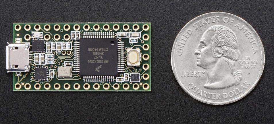
The software to run the Teensy is open source (more on that in Step 3) and the Teensy has a USB port which you connect to your computer which MPF uses to send the display data to the panels.
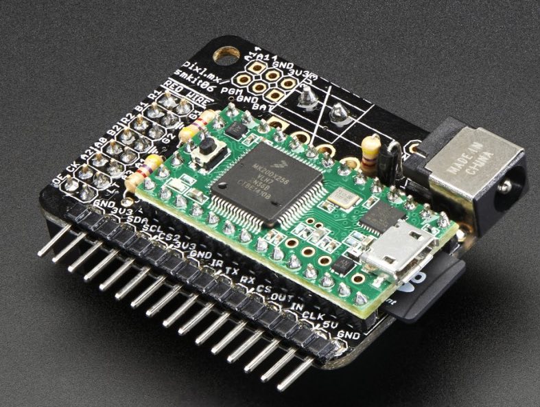
(3) The SmartMatrix Shield
Next you need a way for the Teensy to connect to the displays. That can be done with the SmartMatrix shield (V4 of the shield is \$20 at Adafruit).
The SmartMatrix shield is a "dumb" device that basically just connects the Teensy's GPIO pins to the 16-pin ribbon cable that drives the displays.
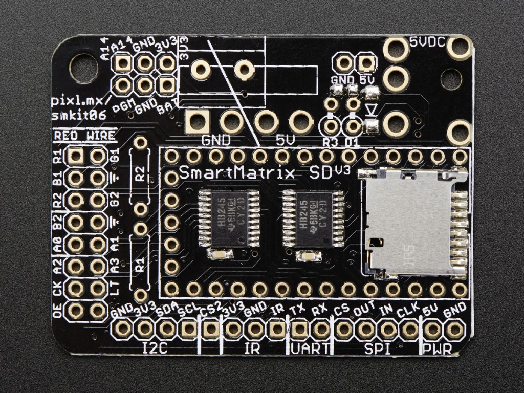
The Teensy mounts onto the SmartMatrix shield, creating a single unit which accepts data via USB on one end and spits out the 16-pin signal for the display panels on the other.
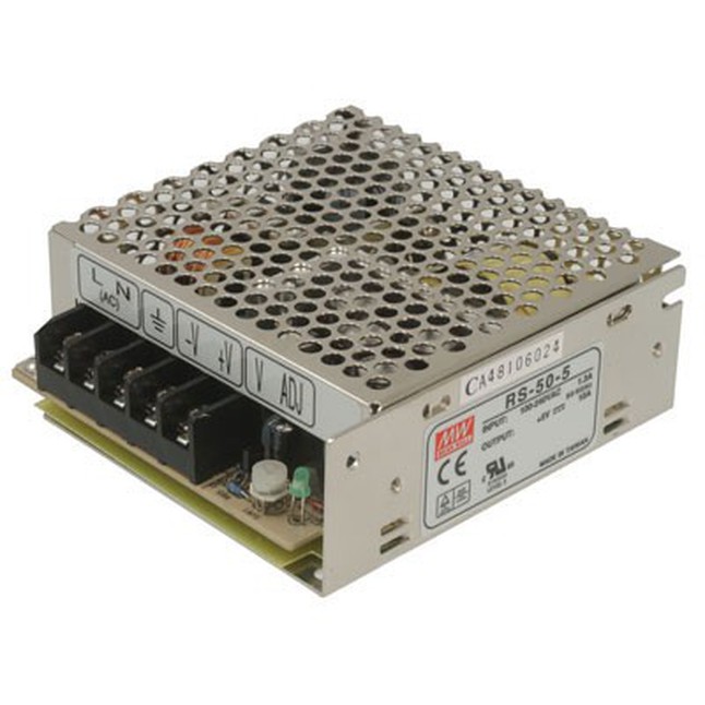
(4) The Power Supply
These RGB LED displays require 5vdc for power. At first you might think, "Cool! I have 5v elsewhere in my machine, so I'll just tap into that!" Not so fast. These displays require a lot of power. After all, each pixel is actually three separate LEDs (one each for red, green, and blue), and a 128x32 display means that you have 4,096 pixels. So that's 12,228 LEDs you need to power!
If you're ordering your RGB LED display panels from FAST Pinball, you can also order a 5v, 10A power supply from them for \$19.
An ATX computer power supply will probably have a decent amount of amps also, so that could be an option too, just check the specs. Any other 5V supply with decent power should also work.
One thing about these RGB LED-based displays is they are bright. Like, really, really bright. (We're talking "burn your retinas if you stare straight at them" kind of bright.)
So even though you can do the math and read that if every pixel is on, full white, 100%, that might take more power than you have, there is no way you're going to run these things at full brightness.
Even at 50% brightness, (which would draw only 50% power) most people find these panels to be too bright. One user runs his at 25%, another at 18%. So it's possible that you might be fine with 5-7 amps of power.
You'll need to connect the power supply up to both panels (the 128x32 display is made up of two 64x32 panels), and while you're at it you can also use it to power your Teensy.
There's a trace you have to cut on the Teensy to control whether it's powered externally or by USB. Don't hook it up to external power if you haven't cut that trace!
2. Load the SmartMatrix code onto the Teensy
Once your hardware's built, you need to load the code onto the Teensy which receives the display data via USB and converts and sends it to the pins connected to the SmartMatrix controller. The people who make the SmartMatrix controller have code sample code available. We just took their sample code, removed all the clutter we don't need, and made it available in the tools folder in the MPF download package. (Here's a direct link to the code which you can use since you probably installed MPF via pip and don't have the download package available.
Also, here's the original sample code we based our code on.
If you are using V4 of the shield, you need to insert this line of code in the first line:
#include <SmartLEDShieldV4.h> // this line must be first
The V4 shield's library uses more RAM which can causes the Teensy 3.2 to crash during animations or video playback. Using a Teensy 3.5 or 3.6 solves this issue as they have more RAM.
Note that the width and height of your display is set in lines 11 & 12. You can change that if you want to use a different size display.
Mark Sunnucks was able to run a 128x64 display by setting the height there and also by changing the DMAs from 4 to 2 in line 14.
Also note that you can set the brightness of the display in this code too. You can control the brightness in MPF as well, but if you know for sure (maybe due to power limitations) that you never want the brightness to go over a certain amount, then you can set it here and it will be "hard coded" into your Teensy. (You can change this and re-flash your Teensy at any time.)
Here's a quick overview of how to install this code onto the Teensy. Full instructions are here.
- Install the Arduino IDE v1.8.5
- Install the Teensyduino add-in which adds support for the Teensy
- Load the smart_matrix_dmd_teensy_code.ino sketch from the mpf/tools folder or this link
- Push the button on the Teensy to put it into programming mode
- Compile & load the code onto the Teensy from the Arduino IDE
3. Configure your SmartMatrix hardware settings
Once you have your hardware all set, you need to add a smartmatrix:
section to your machine-wide config and which tells MPF how to talk to
RGB DMDs that use the SmartMatrix platform.
The main thing you have to figure out is the port that the Teensy uses. On Windows, you can just open Device Manager and see which port appears when you plug in the Teensy.
On Mac or Linux, open up the terminal window and type the following
command: ls /dev/tty* The output of this command will look something
like this on Mac:
/dev/tty.Bluetooth-Incoming-Port
/dev/tty.usbmodem1448891
Or this on linux:
/dev/ttyUSB0
/dev/ttyACM0
The port will be the one that has "usbmodem" in the name on Mac. On Linux it will probably be ttyUSBx or ttyACMx. (The actual number will likely be different on your system.) You can run this command with the Teensy unplugged, then plug it in, then run the command again, and see which port appears.
So on Windows, you'll end up with something like:
hardware:
  rgb_dmd: smartmatrix
smartmatrix:
  smartmatrix_1:
    port: com12
    baud: 2500000
    old_cookie: false
And on Mac or Linux, it will look something like:
hardware:
  rgb_dmd: smartmatrix
smartmatrix:
  smartmatrix_1:
    port: "/dev/tty.usbmodem1448891"
    baud: 2500000
    old_cookie: false
Just enter the baud: and old_cookie: settings like they are in the
example above. These are the settings that are needed for the
SmartMatrix. If you are using the FAST DMD board set baud to
3000000.
3. Add a physical RGB DMD device entry
Once you have your SmartMatrix hardware platform set, you need to create the actual device entry for the RGB DMD and map it back to the SmartMatrix platform.
You do this in the rgb_dmds: section of the machine config. This
section is like the other common sections (switches, coils, etc.) where
you enter the name(s) of your device(s), and then under each one, you
enter its settings.
(And yes, in case you're wondering, it's possible to have more than one physical DMD.)
To do this, create a section in your machine-wide config called
rgb_dmds:, and then pick a name for the DMD, like this:
rgb_dmds:
  smartmatrix_1:
    hardware_brightness: .17
    source_display: dmd
There are several settings you can enter here. (See the rgb_dmds: for details.)
You'll probably also want to configure the brightness, which is a
multiplier from 0.0 to 1.0 that's applied to every pixel that's sent
to the DMD. In other words, the example of brightness: .17 means that
each pixel will be shown at 17% brightness. (These things are crazy
bright!)
Note
If you set the brightness multiplier in the sketch code .INO file you loaded onto the Teensy, then that will multiply the brightness after MPF sends it. In other words, if you set .5 in the config file and .5 in the sketch, then the final brightness will be 25%. You might want to set the absolute max brightness in the .INO file once and then fine-tune it via the config file later.
4. Set a source display
Now that you have everything configured, the last step is to make sure the DMD knows what content to show. In MPF, you do this by mapping a physical DMD to an MPF display.
By default, the DMD will look for a display (in your
displays: section called "dmd".
However you can override this and configure the DMD to use whatever
logical display you want by setting a source_display: setting. (Just
make sure that the width and height of your source display match the
physical pixel dimensions of the DMD or else it will be weird.)
A final config you can test
At this point you're all set, and whatever slides and widgets are shown on the DMD's source display in MPF-MC should be shown on the physical RGB DMD.
That said, all these options can be kind of confusing, so we created a
quick example config you can use to make sure you have yours set right.
(You can actually just save this config to config.yaml in a blank
machine folder and run it to see it in action which will verify that
you've got everything working properly.)
Note
Be sure to change the smartmatrix:port: setting in this example config
to match whatever port your Teensy is connected to.
To run this sample config, you can either run mpf both.
When you run it, do not use the -x or -X options, because either of
those will tell MPF to not use physical hardware which means it won't
try to connect to the Teensy.
Note that the Using an RGB full-color LED DMD guide has more details on the window and slide settings used in this machine config.
hardware:
  rgb_dmd: smartmatrix
displays:
  window:  # on screen window
    width: 600
    height: 200
  dmd:  # source display for the DMD
    width: 128
    height: 32
    default: true
    round_anchor_x: left
window:
  width: 600
  height: 200
  title: Mission Pinball Framework
smartmatrix:
  smartmatrix_1:
    port: com5  # this will most likely be a different port for you
    baud: 2500000
    old_cookie: false
rgb_dmds:
  smartmatrix_1:
    brightness: .2
slides:
  window_slide_1:  # slide we'll show in the on-screen window
    - type: display  # this widget shows the DMD content in this slide too
      effects:
        - type: color_dmd
      width: 512
      height: 128
    - type: text
      text: MISSION PINBALL FRAMEWORK
      anchor_y: top
      y: top-3
      font_size: 30
      color: white
    - type: rectangle
      width: 514
      height: 130
      color: 444444
  dmd_slide_1:  # slide we'll show on the physical DMD
    - type: text
      text: IT WORKS!
      font_size: 30
      color: red
slide_player:
  init_done:
    window_slide_1:
      target: window
    dmd_slide_1:
      target: dmd
What if it did not work?
Have a look at our hardware troubleshooting guide.
Something missing or wrong? You can fix it!
This website is edited by people like you! Is something wrong or missing? Is something out of date, or can you explain it better?
Please help us! You can fix it yourself and be an official "open source" contributor!
It's easy! See our Beginner's guide to editing the docs.
Page navigation via the keyboard: < >
You can navigate this site via the keyboard. There are two modes:
General navigation, when search is not focused:
- F , S , / : open search dialog
- P , , : go to previous page
- N , . : go to next page
While using the search function:
- Down , Up : select next / previous result
- Esc , Tab : close search
- Enter : go to highlighted page in the results