Dual-wound Coils
Related Config File Sections:
Warning
Please ensure that you have established common ground between logic and coil power before turning on high voltage on your coils (especially on homebrew machines). Ignoring this might lock on your coils, overheat them, burn down your house or kill you. We are serious, floating grounds are dangerous. If you are not an electrical engineer read the guide about voltages and power.
In a nutshell: You need to connect your logic ground (5V/12V) and your high voltage ground (48V or 80V). A power entry or power filter board is a convenient solution to solve this (and more) issues.
Always turn all PSUs off when connecting power or you might fry all boards at once. This is generally a good idea but even more important when connecting more than one power supply to a board.
IF YOU DID NOT UNDERSTAND WHAT THIS WARNING MEANS STOP NOW AND TRY TO UNDERSTAND IT. OTHERWISE YOUR HARDWARE WILL LIKELY BURST INTO FLAMES AND YOU NEED TO WAIT A FEW DAYS FOR A REPLACEMENT OR EVEN WORSE IT MIGHT KILL YOU. IGNORING THIS IS THE MOST COMMON CAUSE FOR BROKEN DRIVER BOARDS.
A dual-wound coil is a coil (solenoid) with two windings--one "strong" power (or "main") winding for moving the coil, and a second weaker / lower-power winding for "holding" the coil in the active position.
image:: /mechs/images/dual_coil_no_diode.jpg
Dual-wound coils are typically used for flippers, diverters, gates, and other devices in pinball machines that need a strong initial movement followed by an extended hold period.
There are many places in MPF config files where you need to specify a coil name. Rather than adding dual-wound coil logic in many different sections of MPF, we have a dual-wound coil config where you can specify the settings for a particular dual-wound coil (and give it a new name), and then you can use that dual-wound coil anywhere in MPF that a coil is configured.
Hardware
Dual wound coils are like two coils in one but instead of two times two terminals they only have three terminals. Both coils share one of those terminals. Unfortunately, this is not standardized and different for different types of coils.
To make sure you connect things right you need a multimeter and measure the resistance between all three terminals. It might be wise to remove all free-fly diodes while measuring (or at least make sure to measure the inverse direction). You are looking for the main coil with low resistance (2-20 Ohm) and one with higher resistance (50 to 200 Ohm). You can look up the expected resistance in one of the linked charts in our coil hardware section.
Assumed you now got those three measurements:
- Terminal 1 to 2: 4 Ohm
- Terminal 2 to 3: 124 Ohm
- Terminal 1 to 3: 120 Ohm
What does that mean? It means that your main coil is between terminal 1 and 2 and your hold coil is between terminal 1 and 3. Terminal 2 and 3 is just the sum of the resistance of both coils. In general, the highest of the three readings is the combination you want to remove from your list.
How do you connect that? Typically, driver boards connect your coils to ground so you connect power to the terminal which is common between both coils. In this case this would be terminal 1. Terminal 2 and 3 would be connected to your driver board. See the following picture for example:
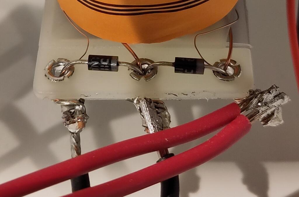
The common terminal on the right (terminal 1) has both wires connected. You see that the diode band is facing in that direction and that two copper wires for the coil are connected here. One wire is a bit thicker, which means less resistance thus more current thus stronger. Hence, the thinner wire is for the hold position. You might not be able to spot that on every coil.
Please note, that you not just connect two wires across each diode. But that one pair of wires is across one diode and the other pair of wires is across two diodes. If you don't do it that way you will fry one of your FETs on the driver board.
Warning
Please make sure that any diodes on your coil are in reverse to the voltage (i.e. the stripe needs to be at the HV side). This is often not the case for older coils as they have been connected differently in older machines. Ignoring this will fry the FET on your driver board.
See coil hardware for more details about the current, resistance, number of windings and the strength of coils.
Config
This is an example for dual-wound coils which are configured separately:
coils:
  c_your_coil_main:
    number: 00   # depends on your platform and hardware
    default_pulse_ms: 20
  c_your_coil_hold:
    number: 01   # depends on your platform and hardware
    default_pulse_ms: 10
    default_hold_power: .2
On top of that you can configure dual_wound_coils: or other devices such as flippers:.
Related How To guides
Something missing or wrong? You can fix it!
This website is edited by people like you! Is something wrong or missing? Is something out of date, or can you explain it better?
Please help us! You can fix it yourself and be an official "open source" contributor!
It's easy! See our Beginner's guide to editing the docs.
Page navigation via the keyboard: < >
You can navigate this site via the keyboard. There are two modes:
General navigation, when search is not focused:
- F , S , / : open search dialog
- P , , : go to previous page
- N , . : go to next page
While using the search function:
- Down , Up : select next / previous result
- Esc , Tab : close search
- Enter : go to highlighted page in the results