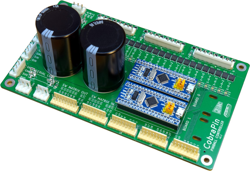
CobraPin Pinball Controller powered by OPP
This section is maintained by the hardware maker
This section of the MPF website is about a specific company's pinball controller hardware, and they are responsible for maintaining the content here.
Of course feel free to edit, add, and/or correct things if you want, but if something seems weird, reach out to the hardware maker, not the MPF maintainers. ;)
Features:
* 24 solenoid outputs broken into 3 banks
* 38 direct inputs <OR> 22 direct inputs + 8x8 switch matrix
* Neopixel support for 512 RGB pixels (RGBW also possible but may be limited to \~460 pixels)
* 24-50V power filter. Board also provides the common ground for the supplies.
* Fuses for solenoid banks and Neopixels
The size of the board is about 197 x 115 mm. Mounting holes are available in the corners of the board, spaced 184 mm and 103 mm respectively. Mounting holes are good for M4 screws.
Overview video about Cobrapin:
Overview video about OPP:
Video about cobrapin extension board:
Power Input and Filter
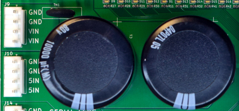
J9:
Solenoid power input (24-50V).
J10:
Neopixel 5V input.
The filter provides consistent power to solenoids while also protecting the power supply from sudden current surges that may otherwise cause a fault. The connectors for the power supply on the board are JST VH style connectors.
Switch Inputs
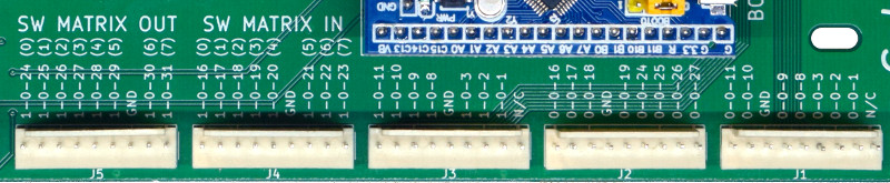
J1, J2, J3:
Direct input switches.
J4, J5:
Remaining direct input switches or switch matrix input/output.
If you do have either 38 direct inputs or 22 direct inputs + a 8x8 switch matrix depends on your Cobra board. You specify this as an option when you order your board. The switch inputs are labeled in silkscreen with the MPF compatible numbers. The two pins labeled "N/C" are not connected to anything.
The connectors for the switches on the board are KF2510 style connectors. For example Molex KK254 series available for AWG 30-22. Each connector also includes a logic ground pin. Use this for the direct input return. If you measure the voltage between GND and a switch (in below picture 0-0-16) you should measure 3.3V.
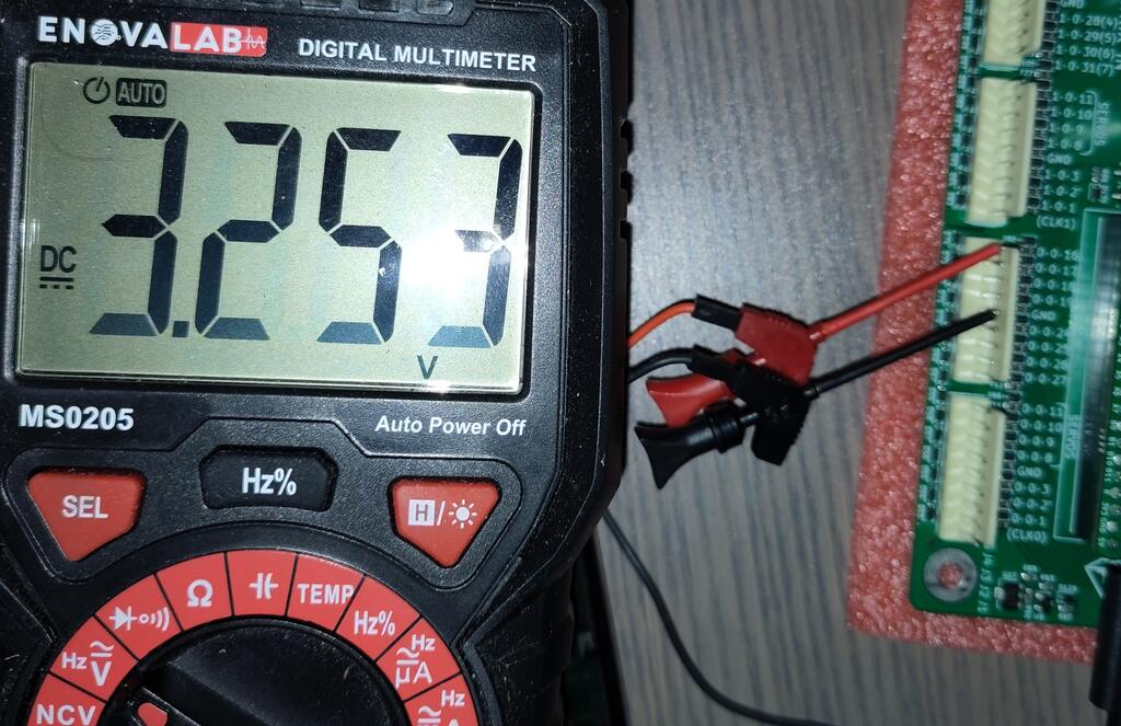
For that to measure only the micro controllers need to be powered up, no need to apply any other voltage on the Cobra board. To perform a simple test connect any kind of switch to one of the inputs and setup a little mpf test configuration.
Do not apply any voltage to the switches, most likely that will destroy your CPU. For further details and fully working Cobra board configuration example please check OPP Switches. For autofire devices please see for additional remarks in the solenoid section below.
Solenoid Outputs

J6, J7, J8:
Solenoid outputs.
The 24 solenoids are broken up into 3 banks of 8 outputs. The connectors for the solenoids on the board are JST VH style connectors. There is a ninth pin on the connector that can be used as a key. Each solenoid has a diode to help protect the transistor. You may still use coils with axial diodes installed, but you MUST ensure that you connect them with the correct polarity.
The solenoid outputs are labeled in silkscreen with the MPF compatible
numbers. OPP coils / drivers. You need to obey that some of these outputs are controlled
by the first micro controller and some by the second. The first digit of
the solenoid number shows by which micro controller it is addressed,
e.g. 1-0-7 is controlled by micro controller 1. This is important
later for the autofire devices (flippers, slingshots, bumpers), because
they are hardware controlled and the switch and the coil must use the
same controller. In other words a coil on 0-x-y of an autofire device
must be controlled by switch with number 0-a-b.
Each bank has an LED next to it to indicate if that bank has power. Check these if you are concerned you have blown a fuse.
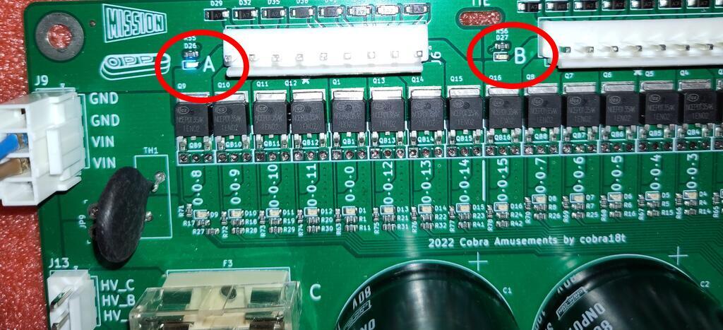
In above picture you see that the LED for bank A is alight but not for bank B. In order to have the LED alight you only need to have connected your high power supply, no need for the 5V power supply or to have micro controllers booted up. Please be aware that once you remove the power supply the LED will still glow for a while until the the capacitors have discharged.
Each solenoid has an associated LED to indicate it is being driven by the processor. It is highly recommended to test a new setup without high voltage power or without the coils plugged in. Using these LEDs, you can verify that each output is being driven correctly, in the picture below coil 1-0-1 is being driven at this very moment.
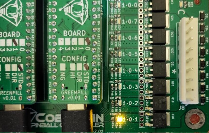
To run the above test, there is no need for a high voltage power supply
neither for any coil. Only the mirco controllers need to be powered up.
The config.yaml below is the only configuration file you need in your
project. The config file is fully valid for the Cobra board connected to
a Linux PC running MPF. If you have a Cobra board but run Windows or
macOS you have to change the ports.
#config_version=5

hardware:
   platform: opp
   driverboards: gen2

opp:
   ports: /dev/ttyACM0, /dev/ttyACM1 # change if your Cobra board uses different ports

coils:
    c_my_coil:
       number: 1-0-1
       pulse_events: s_my_switch_active

switches:
   s_my_switch:
      number: 0-0-16
Some remarks on above config.yaml
- Obey that we don't have an autofire device in this example, and thus the coil and the switch can be connected to the different micro controllers.
- In the coil section
pulse_eventsis being used, don't mix it up withenable_eventswhich would not only pulse the coil but have it on permanently. - When a switch is being activated automatically an event (switch_name)_active is being fired. The above example makes use of this fact.
To have a fully working example for setting up autofire coils see the Autofire Coils section of the documentation.
Solenoid Power Output and Fuses
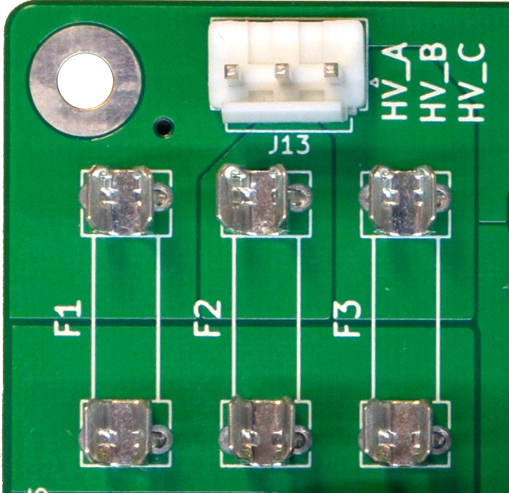
J13:
Solenoid power outputs.
F1, F2, F3:
Solenoid power bank fuses.
The fuses are 5x20mm. Each fuse provides power to a bank of 8 solenoids.
Note
Solenoids in bank A should only be powered by the HV_A pin, bank B should only be powered by HV_B, bank C should only be powered by HV_C. Failure to do so may confuse future troubleshooting and could eventually blow out a transistor.
Neopixel Support
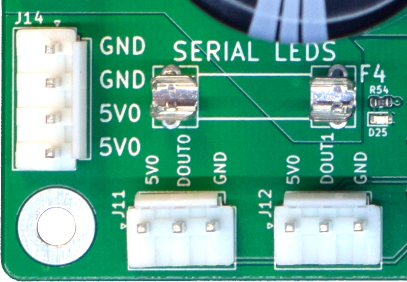
J10:
Power input for Neopixels, most likely 5V, but if you use 12V Neopixels you need to provide 12V power here. Power input is used for both Neopixel chains.
J11, J12:
Neopixel outputs
F4:
5V fuse for neopixels
J14:
Fused 5V output
The connectors J10, J11, J12 and J14 are JST connectors VH style. There are lots of Neopixels which come with a JST connector SM style. You might want to craft a little converter cable in such a case.
![]()
There are two neopixel chains that support 256 RGB pixels each for a total of 512. RGBW pixels are also possible, but the number may be limited to 230 pixels per chain for a total of 460.
The J14 fused output can be used to provide additional power taps in a neopixel chain. Each pin is rated for 7A continuous. The fuse holder is rated for 10A. The red D25 LED can be used to confirm you have a good fuse and are providing power for neopixels. For the LED to light up there is no need to run any MPF configuration, you don't even have to power up the micro controllers.
![]()
When you order the micro controllers you have various options, one option to choose from is Regular vs NoGlow. If you order the Regular version then after power is provided for the Neopixel and the micro controllers are powered up (still no need to run any MPF on them), the LEDs of your strip will glow blue, which is a good first test.
![]()
In order to addess the LEDs in MPF you need to know their address
J11:
NEO 0 Neopixel output, all these lights have MPF numbers with the format 0-0-##. The first LED in the chain is 0-0-0.
J12:
NEO 1 Neopixel output, all these lights have MPF numbers with the format 1-0-##. The first LED in the chain is 1-0-0.
Details on how to configure LEDs in your mpf project can be found here OPP LEDs.
Two fully working example for the Cobra board can be found in the generic LED section LEDs where as well the more general concept is explained.
Microcontrollers
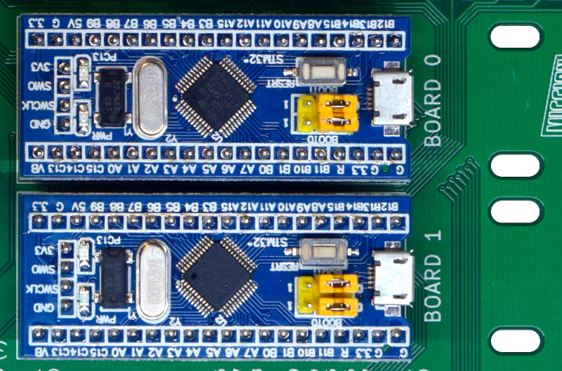
The brains of the CobraPin are two STM32 microcontroller boards programmed with OPP firmware. They are connected to the host computer via micro USB connectors.
Note
It is important to have your config file refer to the silkscreen board numbers (0 and 1) in the correct order, otherwise the labels on the solenoids, switches, etc. will refer to incorrect pin numbers.
The microcontrollers are removable so you can replace them if they fail for whatever reason. They are widely available and often referred to as "STM32 Blue Pill" boards. The right angle header that is normally used as a programming port is replaced with a vertical header so that those pins can be used on the CobraPin board.
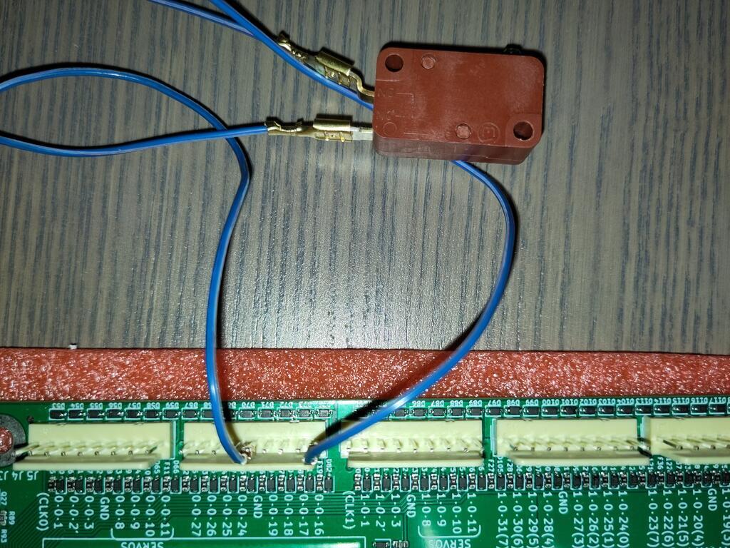
Test Rig
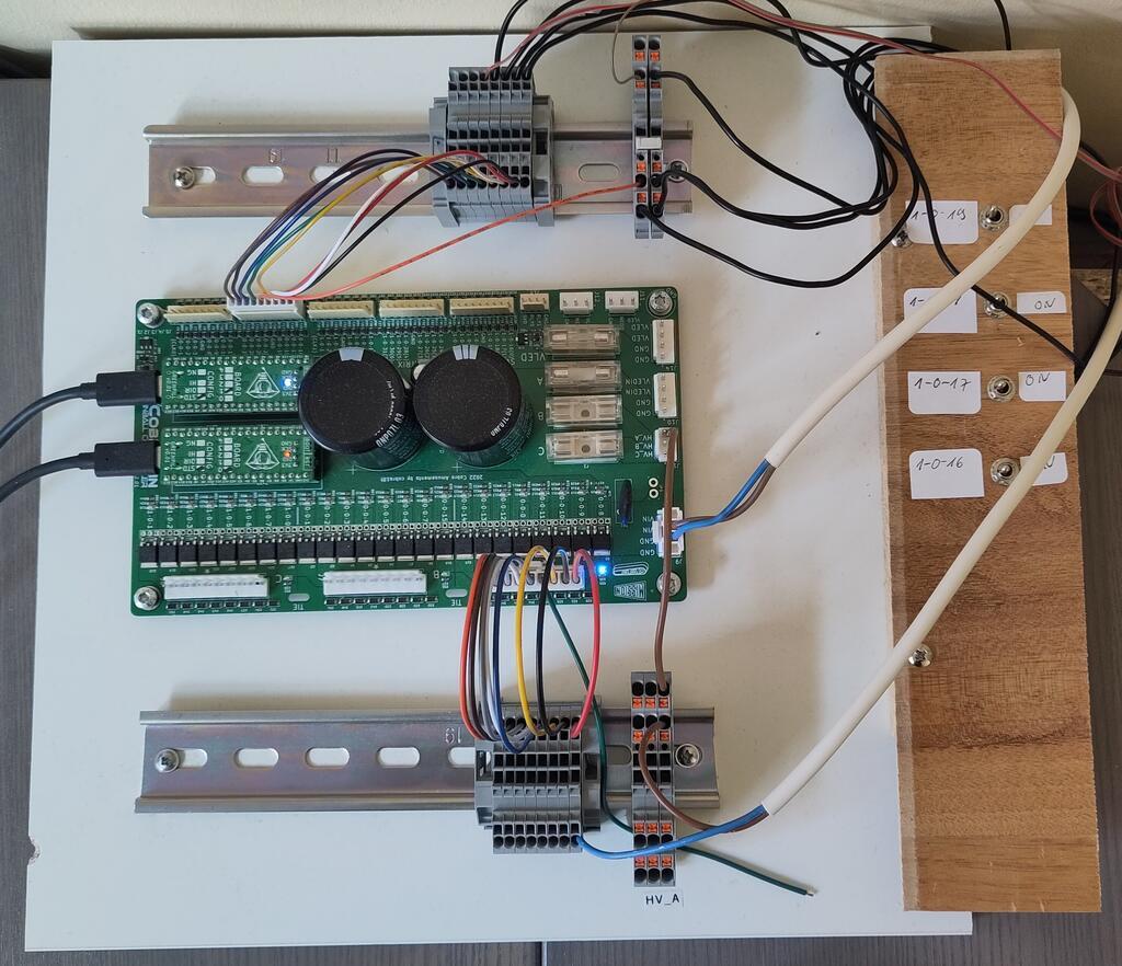
For an easy start you might want to setup a test rig similar to the one shown above. The advantage is that you can use push in clamps to change connected hardware easily without the need to crimp lots of cables. For the connection from the board to the push in clamps you can use pre-fabricated headers with wires, then there is no need to crimp anything.
You can use as well bridges to connect multiple cage clamps together, that might be handy for ground connection. See the two cage clamps at the top right, they have a little bridge (this light grey/white box) to have all inputs internally connected.
Example Config
#config_version=5

#CobraPin Example Config

hardware:
  platform: opp
  driverboards: gen2


opp:
  #Use the USB ports defined by your OS for the two STM32 boards
  ports: /dev/ttyACM0, /dev/ttyACM1
  #USING SERIAL NUMBERS INSTEAD OF CHAINS
  #  Board 0 has serial number 0, Board 1 has serial number 1.
  #  This is convenient if your OS tends to reassign the serial port.
  #  MPF will automatically address the correct board even if the ports
  #     are swapped.

  #For multiple CobraPin boards in a game, you will either have to give
  #  the STM32 boards on the second CobraPin board new serial numbers
  #  (10 and 11 are suggested for the 2nd board since 2 is used by the
  #  CobraPin Xpansion Board)
  #  <OR> Use the chains section to assign a port to a board number.
  #  Mixing these up could cause blown FETs, coils, and fuses. Proceed
  #  with caution. Test without coil power and use the yellow coil LEDs
  #  for feedback.
  #chains:
     #0: /dev/ttyACM0
     #1: /dev/ttyACM1


psus:
  default:
    #Gives the capacitors extra time to recharge after firing a coil
    #  and eases the load on the power supply. Doesn't affect autofire
    #  devices like flippers, pops, slings.
    release_wait_ms: 50


#One giant config file can get difficult to manage. You can put any of
#  these config sections in its own yaml file and link to it with the
#  config section here
config:
  #- switches_config.yaml
  #- lights_config.yaml
  #- coils_config.yaml
  # ...


switches:

  #DIRECT SWITCHES
  #switch numbers are labelled in silkscreen on the board
  s_left_flipper:
    number: 0-0-27
    tags: left_flipper
  s_right_flipper:
    number: 0-0-26
    tags: right_flipper
  s_startButton:
    number: 0-0-25
    tags: start


  #MATRIX SWITCHES
  #valid numbers are 1-0-32 through 1-0-95
  s_lowerDrop1:
    number: 1-0-32

  # ...

  s_topRollunder:
    number: 1-0-95
    ignore_window_ms: 250ms    #tune to assist in debouncing


lights:

  #SERIAL LEDS (neopixels)
  #NEO0 output supports 256 LEDs numbered 0-0-0 to 0-0-255
  l_shootAgain:
    number: 0-0-0
    subtype: led
    type: grb   #Most WS2812-based LEDs are grb color order.
                #This line not required for rgb ordered LEDs like the
                #  WS2811 LEDs shown below

  # ...

  #NEO1 output supports 256 LEDs numbered 1-0-0 to 1-0-255
  l_gi_1:
    number: 1-0-0
    subtype: led
    tags: gi    #you can group similar LEDs with user defined tags
  l_gi_2:
    number: 1-0-255
    subtype: led
    tags: gi


coils:
  #coil numbers are labelled in silkscreen on the board

  #There are multiple ways to configure flippers, use the one that
  #  matches your hardware
  c_flipper_left:
    number: 0-0-8
    allow_enable: true
    default_hold_power: 1.0
    default_pulse_ms: 50
  c_flipper_right:
    number: 0-0-4
    allow_enable: true
    default_hold_power: 1.0
    default_pulse_ms: 50
  c_ballRelease:
    number: 1-0-1
    default_hold_power: 0.15
    default_pulse_ms: 30


flippers:
  #Add your flipper config


autofire_coils:
  #Add your autofire cofigs for pops, slings, etc.


ball_devices:
  #Add your ball devices


playfields:
  #Define your playfields


machine:
  balls_installed: 3 #How many balls are physically in your game
  min_balls: 3 #How few balls can be accounted for before you can start a game


game:
  balls_per_game: 3
  max_players: 4


modes:
  #Add all your mode names here
  #- attract
  #- base
  #- etc


keyboard:   #use to drive your game from the computer for testing
  z:
    switch: s_left_flipper
  "/":
    switch: s_right_flipper
Something missing or wrong? You can fix it!
This website is edited by people like you! Is something wrong or missing? Is something out of date, or can you explain it better?
Please help us! You can fix it yourself and be an official "open source" contributor!
It's easy! See our Beginner's guide to editing the docs.
Page navigation via the keyboard: < >
You can navigate this site via the keyboard. There are two modes:
General navigation, when search is not focused:
- F , S , / : open search dialog
- P , , : go to previous page
- N , . : go to next page
While using the search function:
- Down , Up : select next / previous result
- Esc , Tab : close search
- Enter : go to highlighted page in the results