Mechanical Switches
Related Config File Sections:
Most switches in pinball machines are mechanical switches which are open by default and close a circuit when pushed.
Video about wiring switches:
There are two common types of mechanical switches:
Leaf switches/Blade switches
First, blade switches which are very cheap and reliable but cannot be used everywhere:
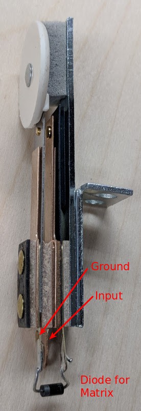
Typically, those are use for flipper buttons and flipper end of stroke switches.
Part numbers:
- Stern Flipper Leaf Switch: 500-6889-01 or 500-6890-01
- Data East/Sega Flipper Leaf Switch: 180-5122-00
- Williams/Bally Flipper Leaf Switch: SW-10A-48 or SW-1010A-13
- Data East End of Stroke Switch: 180-5018-00
- Williams/Classic Stern/Bally End of Stroke Switch: SW-10A-50, ASW-A20-23, SW-1A-193
Additionally, those are used for targets:
Part numbers (Data East/Sega/Stern):
- 515-5966-xx
- 500-5835-xx
- 515-5124-xx
- 500-5232-xx
- 515-5162-xx
- 515-5967-xx
- 515-6027-xx
xx defines the color of the target in most cases.
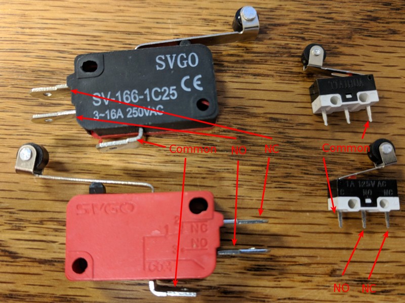
Micro switches
Second, micro switches which are very small and commonly used for roll over switches. Those usually have three connectors:
C- common pin forNOandNCNO- normally open - connected toConly when the switch is pressedNC- normally closed - connected toConly when the switch is not pressed
Usually, you connect C to ground and NO to your direct input (see
below for switch matrices).
Electronically and logically both switches work similarly.
Part numbers (Data East/Sega/Stern):
- 180-5010-xx
- 180-5053-xx
- 180-5119-xx
- 180-5118-xx
- 180-5052-xx
- 180-5186-xx
- 180-5057-xx
- 500-5442-xx
- 180-5175-xx
xx defines the shape of the blade for most parts.
Direct inputs
Switches can be connected to a direct input and ground on almost all platforms. Most direct inputs have an internal pull up which will pull the level to VCC (usually around 10 kOhm). When pushed the switch will pull the input to ground which will be detected as a closed switch by the platform.
TODO: Add electronical drawing for switch on direct input.
Switch matrix
Additionally, you can use switches in a switch matrix. In a switch matrix columns are connected to drivers and rows to switches. Columns are then pulsed sequentially and the rows are read. Each switch has to use a diode to prevent closing other columns.
TODO: Add electronical drawing for switch in matrix.
Switch matrices are driven using your hardware platform and MPF will read the values from the platform. Usually the numbers for switches reflect their row and column in the matrix. Consult your hardware platform documentation for details.
MPF Config
This is an example of switches in MPF:
switches:
  my_direct_switch:
    number: 23        # number depends on your platform
  my_matrix_switch_row_1_column_3:
    number: 1/3       # number depends on your platform
Something missing or wrong? You can fix it!
This website is edited by people like you! Is something wrong or missing? Is something out of date, or can you explain it better?
Please help us! You can fix it yourself and be an official "open source" contributor!
It's easy! See our Beginner's guide to editing the docs.
Page navigation via the keyboard: < >
You can navigate this site via the keyboard. There are two modes:
General navigation, when search is not focused:
- F , S , / : open search dialog
- P , , : go to previous page
- N , . : go to next page
While using the search function:
- Down , Up : select next / previous result
- Esc , Tab : close search
- Enter : go to highlighted page in the results