Connecting your computer
Connecting your computer to the Stern SPIKE CPU node
Related Config File Sections:
There are at least 3 options to connect a computer running MPF to the SPIKE CPU via a serial connection.
- USB to USB Null Modem Cable
- USB to Serial Adapter
- Using two USB to Serial Adapters
OPTION 1: USB to USB Null Modem Cable
Probably the cleanest and easiest method is to purchase the USB to USB Null Modem Cable. With this cable, you can plug one end into the USB port on your computer and the other end into one of the two USB ports on the SPIKE board. On a Windows computer, use the Device Manager to determine which COM port the cable has been assigned by Windows. Update you machine configuration with the correct COM port (example, COM5).
spike:
  port: COM5
Null modem cables used to be a common way to connect two computers together. This is the most expensive solution at about \$50 USD. However it looks just like a USB cable. The only vendor that has the USB to USB Null Modem Cable is the FDTI company.
https://ftdichip.com/products/usb-nmc-2-5m/
This particular cable also provides faster data transfer rates (up to 3 MBaud) than Options 2 and 3.
OPTION 2: USB to Serial Adapter
The second method is to purchase a USB-to-serial adapter and connect it to the DBGU header (CN2) on the SPIKE CPU node. The problem you may have is that not all SPIKE boards have the header soldered onto the board. A header is essentially a 6 pin socket that the adapter can plug into. If you do have the header at location CN2, great! Read on.
Ok, you have a header on the SPIKE board. Simply purchase an inexpensive USB to serial adapter and plug it in. There are lots of them, most for less than \$10, and they're all pretty much the same.
Some examples that should work (though we don't guarantee it and we're happy to hear feedback or recommendations):
https://www.amazon.com/FICBOX-CP2102-Serial-Downloader-Arduino/dp/B01CU12324/ https://www.amazon.com/HiLetgo-CP2102-Module-Serial-Converter/dp/B00LODGRV8 https://www.amazon.com/HiLetgo-Ft232rl-Serial-Adapter-Arduino/dp/B00IJXZQ7C https://www.adafruit.com/products/3309 https://www.sparkfun.com/products/12731 https://www.sparkfun.com/products/13830
Make sure you have a 3.3v adapter (or that your adapter can be set for 3.3v).
Note
If you're using a Raspberry Pi, you can use its built-in serial pins and don't need a USB-to-serial adapter.
Connecting using DBGU
Connect the USB serial adapter to the DBGU header (CN2) on the SPIKE CPU node.
Pins are marked GND, RX, TX. You do not need more than these.
Help us write it!
This section is unwritten or needs an update or edit. Can you help write it? Get your name in lights and geeky pinball bragging rights! Hit the magic sparkly wand to the right of the title to see this page source on GitHub. Then add/edit and submit your change. It's easy!
Unfortunately, this header seems to be missing on some revisions of Spike. You can solder it in though. However, it does not contain any flow-control pins to it will not work at higher baud rates (up to 400k roughly).
OPTION 3: Connect using two USB-Serial Adapters
Newer versions of the SPIKE CPU node do not have a connector attached to the CN2/DBGU header. The newer board is the same, but you see a blank spot instead of the plug-in connector attached. If you do not want to solder a header onto the SPIKE board then you need to go back to Option 1 or use this option. Soldering on the SPIKE board is risky if you lack experience with a solder iron and will likely void your warranty.
For this option, you can buy two USB serial adapters and then use the USB connection on the SPIKE CPU node.
The one you connect to the SPIKE CPU node needs to have an actual FTDI brand chip because the FTDI drivers are included in the code on the SPIKE board. The second adapter for your computer can be any brand since it's easy to install whatever drivers it needs on your computer. Whatever serial port appears on your computer when you plug in this adapter is the port name you'll use in your machine config.
These two adapters will have connectors or headers on them that you need to connect together. Connect the "RX" (receive) from one to the "TX" (transmit) on the other and vice-versa. Also connect the grounds (possible labeled "GND") together. It's probably a good idea to twist the wires together to reduce interference, especially if your wires are more than a few inches long.
In addition to above you should also "CTS" to "DTS" and "DTS" to "CTS". This will allow you to enable hardware flow control which is essential at higher baud rates (up to 3M).
The following diagram illustrates how everything fits together:
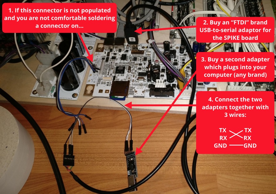
You've essentially created a null modem cable as described in Option 1. This option may be a little cheaper but the solution is far less elegant and stable.
What if it did not work?
Have a look at our SPIKE troubleshooting guide.
Something missing or wrong? You can fix it!
This website is edited by people like you! Is something wrong or missing? Is something out of date, or can you explain it better?
Please help us! You can fix it yourself and be an official "open source" contributor!
It's easy! See our Beginner's guide to editing the docs.
Page navigation via the keyboard: < >
You can navigate this site via the keyboard. There are two modes:
General navigation, when search is not focused:
- F , S , / : open search dialog
- P , , : go to previous page
- N , . : go to next page
While using the search function:
- Down , Up : select next / previous result
- Esc , Tab : close search
- Enter : go to highlighted page in the results