How to configure LEDs on the PD-LED (P-ROC/P3-ROC)
Related Config File Sections:
This guide explains how to configure MPF to use LEDs attached to a Multimorphic PD-LED board with either a P-ROC or P3-ROC.
Note that if you're using a P-ROC/P3-ROC and you want to use serial-controlled LEDs (NeoPixels, etc.), then you can do that with a P-ROC/P3-ROC by using a FadeCandy instead of a PD-LED. You can also mix-and-match PD-LEDs and FadeCandy LEDs. If you are using a PD-8x8 or a local matrix on the P-Roc see the instructions about Matrix lights for P/P3-Roc.
Channel and Number Syntax
In MPF lights abstract
a light source which emits arbitrary colors. However, this is not true
for all real lights. Some support only white (GIs), others only a
single-color (i.e. red inserts) and others support full RGB. For that
reason MPF knows
light numbers and channel numbers. Internally, a light consists of one or multiple channels.
For instance, a single-color GI will contain a single white channel.
While a RGB light will control a red, green and a blue channel. A white
light behind a red insert should be a single red channel (because it
cannot emit other colors through the red insert). You can configure
those channels using the channels setting or use start_channel and
type to define the channels. See
/mechs/lights/index for details.
However, in most cases a platform supports one type of lights (per
subtype) this would be overly verbose and we added the number
setting for configuring lights in the common platform way. For instance
a platform for GIs will configure single channel white lights or a
serial LED controller will configure RGB lights with three channels.
The PD-LED assumes that you want to use RGB LEDs by default. For anything else you have to use channels.
Light Numbers
PD-LED numbers use the format:
board_number-led_index1-led_index2-led_index3
Since the PD-LED board directly drives single color LED outputs, when you use it with RGB LEDs, you combine three outputs into a single RGB LED. The PD-LED supports both common cathode (common ground) and common anode (common 3.3v) LEDs, so each LED you buy has four pins (red, green, blue, and common). When you configure the hardware number for a PD-LED RGB LED, you specify four parts, separated by dashes:
- The address of the PD-LED board on the serial chain (as configured via the DIP switches on the PD-LED.
- The output number of the red element.
- The output number of the green element.
- The output number of the blue element.
You separate those with dashes, so an example PD-LED configuration might look like this:
lights:
  l_led0:
    number: 8-0-1-2
    subtype: led
The example above configures "l_led0" as the LED connected to PD-LED board at address 8, using outputs 0, 1, and 2 as its red, green, and blue connections.
subtype: led is only needed on the P-Roc since subtype defaults to
led on the P3-Roc defaults. The P-Roc defaults to matrix.
Channels
Channels use the format: board_number-led_index
This is almost the same as above but it addresses only one output (instead of three). You can use the channel syntax as for l_led0 above:
lights:
  l_led0:
    channels:
      red:
        - number: 8-0
      green:
        - number: 8-1
      blue:
        - number: 8-2
You might connect different color channels to your PD-LED. For instance you might have only a red channel:
lights:
  my_red_only_insert:
    channels:
      red:
        - number: 8-0       # board 8 and first channel
Or you can configure a white LED:
lights:
  my_white_light:
    channels:
      white:
        - number: 8-4
Starting from MPF 0.54 you can also have MPF calculate the numbers for you:
lights:
  led_0:
    start_channel: 8-0
    subtype: led
    type: rgb    # will use red: 8-0, green: 8-1, blue: 8-2
  led_1:
    previous: led_0
    subtype: led
    type: rgbw   # will use red: 8-3, green: 8-4, blue: 8-5, white: 8-6
  led_2:
    previous: led_1
    subtype: led
    type: rgbw   # will use red: 8-7, green: 8-8, blue: 8-9, white: 8-10
You can also configure two red channel, green plus white or any other combination. See LEDs for more details about how to configure channels for different types of LEDs.
Understanding the PD-LED board
The PD-LED controls up to 84 individual LED elements, which can be used to control individual single color LEDs, or (more likely), combined into groups to control RGB LEDs.
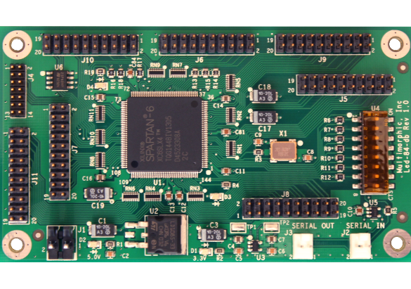
The PD-LED uses a "direct/parallel" connection method for LEDs, where each LED has connections for each color element running back to the PD-LED. This requires at least two wires per LED (or four for RGB LEDs). In addition you can also use serial LEDs starting with PD-LED v2 (see below).
Parallel LEDs
Those LEDs are wired individually to the PD-LED.
This is an example:
lights:
  l_led_1:
    number: 4-0-1-2
    subtype: led
LED number:
You can use number 0 to 83 to address your LEDs. The number format is defined above.
Polarity
The PD-LED allows you to use either common anode or common cathode LEDs. (See the PD-LED documentation for details. The type of LED would dictate whether you hook it up between the PD-LED's output and ground, or between the output and 3.3v.) You can then use the config file to specify which type of LED you have, such as:
lights:
  l_shoot_again:
    number: 8-60-61-62
    platform_settings:
      polarity: true
True = common cathode (or common ground), False = common anode (or common 3.3V)
Note that DIP Switch 6 on the PD-LED board controls whether the "default" state of the LEDs after a reset is high or low. Basically it's whether all the LEDs turn on or turn off when the board is reset. Which position does what is dependent on whether you're controlling the anode or the cathode with your outputs, so basically if you turn on your PD-LED and all your LEDs turn on, then flip DIP switch 6 on the PD-LED to the opposite position and power cycle the board. Note: If servos are connected to a PD-LED board, DIP switch 6 also effects servo signal on power up. See Servos on a PD-LED (P-ROC/P3-ROC) for additional information.
Breakout boards for parallel LEDs
You likely want to buy or build some breakout boards for your LEDs when you are using parallel LEDs in your machine. Otherwise, you might end up in wiring hell for your lights. Luckily, there breakout boards exist which connect via a ribbon cable to your PD-LED.
Breakout boards:
- Four LEDs breakout (Multimorphic) - PCBA-0025-0002
- Five equally spaced LEDs + three LEDs breakout (Multimorphic) - PCBA-0030-0001
- Breakout wire harness (PBL) for four LEDs - #600-0274-00
Part numbers of lights and flashers:
- GI RGB LED (PBL) - #600-0230-00
- RGB Insert LED (PBL) - #600-0220-01
- RGB Insert LED (Multimorphic) - PCBA-0004-0001
- Flasher (Multimorphic) - PCBA-0024-0001
- Pop bumber RGB LED (PBL) - #600-0258-00
Additionally, they got a PCB with five equally spaced LEDs which breaks out another three LEDs (part number: ). Make sure to check those out because it will make your live easier. In your final machine you will probably build some larger PCBs and connect them using ribbon cables.
Serial LEDs on the PD-LED
Overview video about serial LEDs:
Starting with PD-LED v2 you can use the PD-LED to drive serial LEDs. To
enable a serial LEDs you need to configure your PD-LED board in your
p_roc section. Assuming your PD-LED has the address 4 you can use the
following config to enable all serial LEDs and and define a few:
p_roc:
  pd_led_boards:
    4:
      use_lpd880x_0: true
      use_lpd880x_1: true
      use_lpd880x_2: true
      use_ws281x_0: true
      use_ws281x_1: true
      use_ws281x_2: true
lights:
  l_serial_chain_0_first:
    start_channel: 0-100
    type: rgb
    subtype: led
  l_serial_chain_0_second:
    previous: l_serial_chain_0_first
    type: rgb
    subtype: led
  l_serial_chain_1_first:
    start_channel: 4-250
    type: rgb
    subtype: led
  l_serial_chain_2_first:
    start_channel: 4-400
    type: rgb
    subtype: led
LED number:
By default MPF maps the first chain (of both LPD880x and WS281x) to LEDs 100 to 249. The second chain to 250 to 399 and the third to 400 to 599. You can change those settings in the pd_led_boards: section.
The number format is the same as for parallel LEDs (see above). Board number is the number the at the PD-LED's DIP switches. Index is the number of your LED (starting at 0) in the chains plus the chain start offset (100 for the first chain, 250 for the second or 400 for the third).
Color Correction
If you are using RGB LEDs, they might not be perfectly white when you turn them on. They might be pinkish or blueish instead depending on the brand of the LED. To a certain extend this is normal/expected and you can compensate for it by configuring color_correction profiles in light_settings.
Amplifying PD-LED channels with FETs
PD-LED drives LEDs with a current of 22mA. Also, it cannot exceed its output voltage of 3.3 V effectively limmiting it to a single LED per channel. If you want to drive more LEDs on a channel (e.g. GIs or long strips) you can connect a MOSFET (as stated in the manual). Choose a logic-level N-Channel MOSFET with an Output Characteristics curve showing current saturation meeting the needs of the strip with a voltage between the gate and source (VGS) of 3.3 V or less. This is an example of such a circuit:
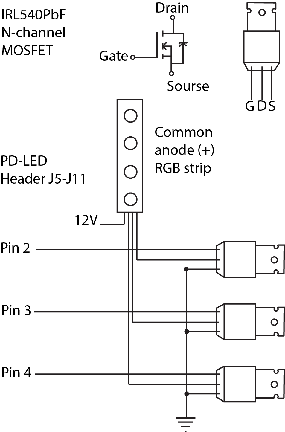
Please make sure to connect your PD-LED and the FET to the same common ground or your FET will smoke when connecting power.
What if it did not work?
Have a look at our troubleshooting guide for the P/P3-Roc.
Something missing or wrong? You can fix it!
This website is edited by people like you! Is something wrong or missing? Is something out of date, or can you explain it better?
Please help us! You can fix it yourself and be an official "open source" contributor!
It's easy! See our Beginner's guide to editing the docs.
Page navigation via the keyboard: < >
You can navigate this site via the keyboard. There are two modes:
General navigation, when search is not focused:
- F , S , / : open search dialog
- P , , : go to previous page
- N , . : go to next page
While using the search function:
- Down , Up : select next / previous result
- Esc , Tab : close search
- Enter : go to highlighted page in the results